Image quality and artifacts in coronary CT angiography
David F. Cuevas Cueto, MD · Updated September 27, 2026 · Sources: SCCT 2026 and CAD-RADS 2.0
Before grading a stenosis, you need to know how much the images can be trusted. This section covers the overall quality scale, the nonevaluable segment and the artifacts that can mimic or hide disease, following the SCCT 2026 consensus. The use of N as a category or as a modifier is explained in the CAD-RADS section.
Key points
Overall quality is graded on a visual scale, for example from excellent to non-diagnostic, and is reported with the artifacts present, their effect and any mitigation performed.
If a segment 1.5 mm in diameter or larger cannot be interpreted, the report names the segment and the artifact responsible.
Before calling a segment nonevaluable, review the other phases and reconstructions, because many artifacts change or disappear in them.
Respiratory or body motion also displaces the sternum and spine and, unlike cardiac motion, is not corrected by reconstructing another phase.
Over dense calcium, report the highest visible stenosis grade, with the caveat that blooming may overestimate it.
A low-attenuation band next to calcium, a stent or dense contrast may be a beam-hardening artifact and can mimic non-calcified plaque or a perfusion defect.
Table 1. Common artifacts in coronary CT angiography: their appearance, what they can mimic and how to recognize them at the workstation.
Artifact
Appearance
What it can mimic
How to recognize it
Cardiac motion
Blurred vessel, especially in the vertical segment of the RCA
Stenosis; it can also hide a lesion
The sternum and spine are not displaced, and the vessel changes or becomes sharp in another phase
Respiratory or body motion
Displacement of all structures between slabs
Stenosis or vessel discontinuity
The sternum and spine are also displaced, and another phase does not correct it
Misalignment (stair-step)
Horizontal step at the boundary between slabs
Stenosis or focal vessel discontinuity
Best seen on sagittal and coronal planes; the line crosses the whole heart
Blooming (calcium or stent)
Calcium or stent struts appear thicker, with blurred edges
More severe stenosis or in-stent restenosis
Decreases with a wider window, thinner slices or a sharper kernel
Beam hardening
Low-attenuation area or band next to calcium, metal or dense contrast
Non-calcified plaque, in-stent neointimal hyperplasia or a perfusion defect
Arises from the dense structure, varies between phases and decreases on high-energy images
Noise
Grainy texture with random bright and dark streaks
Does not mimic disease, but hides non-calcified plaque
Also affects homogeneous tissue and improves with thicker slices or a smoother kernel
Suboptimal enhancement or contrast mixing
Lumen of low or uneven attenuation
Non-calcified plaque or stenosis
No wall thickening, and it changes between phases or with another window
Source: SCCT 2026, section «Image quality, artifacts & pitfalls», pp. 24–29; myocardium, p. 31; Table 4, p. 50.
Because there is no established standard, SCCT 2026 recommends grading the whole study on a visual scale, for example excellent, good, average, fair, poor or non-diagnostic.
In practice. It is reported in the findings, before the arteries are described. SCCT 2026 asks that it be accompanied by the artifacts present: their type, their effect on interpretation and any mitigation performed.
Pitfall. Assigning category N only because overall quality is poor is incorrect. N depends on the segments that could not be interpreted.
Other sources. The CAD-RADS 1.0 report template tied each level of technical quality to artifacts. An excellent study had no artifacts, a good one had minor artifacts, an adequate one had moderate artifacts and a poor or suboptimal one had severe artifacts. SCCT 2026 proposes six levels and defines none of them. (CAD-RADS 1.0, Fig. 16)
On the map. The «Study quality» selector offers those six grades and opens the findings with a line such as «Study quality: good.» It does not change the category, and each nonevaluable segment is marked separately with «N».
Source: SCCT 2026, Reporting, section d «Image quality and findings», and Table 6, pp. 35 and 52 · «With no established standards for overall study quality, a visual schema such as excellent, good, average, fair, poor or non-diagnostic is recommended.»
Also seen as:non-evaluable segment, nonevaluable segment, non-assessable segment, uninterpretable segment
A segment 1.5 mm in diameter or larger is non-interpretable (nonevaluable) when an artifact prevents confident interpretation. The guideline asks you to name the segment and the artifact that causes it.
In practice. Before calling it nonevaluable, review the other phases, other planes and another window. If it still cannot be interpreted, write, for example, «mid RCA nonevaluable due to motion artifact». Its effect on the category is explained in the CAD-RADS section.
Pitfall. Reporting «nonevaluable segment» without saying why leaves the referring physician unaware of what limited the study. The guideline asks you to name both the segment and the artifact.
Other sources. For plaque quantification, SCCT 2024 takes image quality and vessel caliber into account. It excludes segments with severe artifacts. A large proximal segment with moderate artifacts may be analyzed, whereas a small distal segment with mild artifacts may not. (SCCT 2024, section 2.2)
On the map. The «N» button in the editor marks the segment, clears its plaque and shows it frosted. The template gives a generic cause, «nondiagnostic image quality», and the specific artifact is added when the text is edited. Open the example on the map (CAD-RADS N/P1) →
How the map's template words it
Study quality: fair.
Left anterior descending (LAD): proximal segment: non-calcified plaque causing mild stenosis (25-49%); the remainder is unremarkable. Branches D1, D2: no plaque.
Right coronary (RCA): mid segment: nonevaluable due to nondiagnostic image quality; the rest of the vessel is unremarkable. Branches AM, R-PDA, R-PLB: no plaque.
Impression Nondiagnostic study for obstructive CAD. CAD-RADS N/P1.
Source: SCCT 2026, Reporting, section d «Image quality and findings»; also stenosis section, p. 15 · «Whenever coronary segments are not interpretable, the affected segments and the causative artifact should be stated.»
Also seen as:motion artefact, motion-related artifact
Cardiac, respiratory or body motion during acquisition blurs the vessel contours. Cardiac motion mostly affects the vertical, highly mobile segment of the RCA.
In practice. First check the anterior chest wall and the spine. If they shift between slabs, the cause is respiratory or body motion, which can only be corrected by repeating the acquisition. If not, reconstruct another phase, often systolic when the heart rate is high.
Pitfall. Grading a blurred segment without reviewing another phase is an error, because motion can both mimic and hide lesions. If the blurring does not resolve, the segment is nonevaluable.
Other sources. SCCT 2014 attributed vessel blurring to motion within a single heartbeat and noted that other reconstructions sometimes correct it. Motion between heartbeats, including respiration and body motion, instead produced the stair-step artifact, now called misalignment artifact. (SCCT 2014, section 5.1.1)
On the map. The map does not record the artifact type. If motion prevents interpretation of a segment, mark it with «N» and, when editing the template, replace the generic cause with «motion artifact». Open the example on the map (CAD-RADS 3/P1/N) →
How the map's template words it
Study quality: average.
Left anterior descending (LAD): mid segment: partially calcified plaque resulting in moderate stenosis (50-69%); the remainder is unremarkable. Branches D1, D2: no plaque.
Right coronary (RCA): mid segment: nonevaluable due to nondiagnostic image quality; the rest of the vessel is unremarkable. Branches AM, R-PDA, R-PLB: no plaque.
Source: SCCT 2026, Image quality, artifacts & pitfalls, c. Motion artifacts, pp. 25–26 · «Cardiac motion appears as vessel blurring, most commonly in the highly mobile vertical segment of the right coronary artery»
Also seen as:misregistration artifact(Discouraged by SCCT 2023), registration artifact(Discouraged by SCCT 2023), step artifact(Discouraged by SCCT 2023), transition artifact
Misalignment is an abrupt offset of structures at the boundary between slabs acquired in different heartbeats, usually caused by an irregular rhythm or incorrect ECG gating.
In practice. Look for it on sagittal and coronal reconstructions, where the step is a horizontal line crossing the entire heart. If a pseudolesion is suspected, reconstruct another phase or turn off edge correction, which reveals the true boundary between slabs.
Pitfall. Grading a narrowing that coincides with the boundary between two slabs can produce a false positive. Confirm it first in another phase or without edge correction.
Other sources. The SCCT 2023 standardized terminology recommends «misalignment artifact» and discourages the older names «stair-step», «registration» and «misregistration» artifact. SCCT 2026 calls it transition, stair-step or misalignment artifact. (SCCT 2023 terminology, Table 4)
On the map. The map has no dedicated control for this artifact. A segment that still cannot be interpreted is marked with «N», and in the template the generic cause is replaced with «misalignment artifact».
Source: SCCT 2026, Image quality, artifacts & pitfalls, c. Motion artifacts, p. 26 · «Transition (stairstep or misalignment) artifacts occur at slab interfaces from different cardiac cycles, typically due to irregular rhythm or incorrect rhythm gating»
Also seen as:calcium blooming(Discouraged by SCCT 2023), partial volume averaging(Term preferred by SCCT 2023), blooming artefact
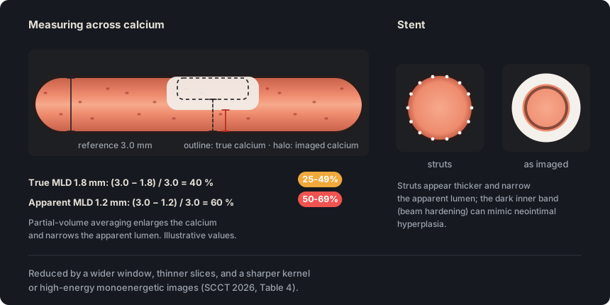
Partial volume averaging within each voxel blurs the interface between the lumen and calcium or a stent. The dense material appears larger and the stenosis is overestimated.
In practice. Review thin slices with a sharper kernel, or high-energy monoenergetic images if available. Over dense calcium, report the highest visible grade with the caveat of possible overestimation. A stent whose lumen cannot be distinguished is reported as nonevaluable for restenosis.
Pitfall. Measuring stenosis over dense calcium with the usual window exaggerates blooming. For that measurement, widen the window until the calcium edge is distinguishable.
Other sources. The SCCT 2023 standardized terminology prefers «partial volume averaging» and considers «calcium blooming» a legacy term that is not recommended. SCCT 2026 and CAD-RADS 2.0 keep «blooming», the term used in this glossary. (SCCT 2023 terminology, Table 4)
On the map. With «Calcified» plaque from 50 to 99 %, the template adds the blooming caveat and, in the impression, a line to consider CT-FFR or functional testing. A stent marked «N» is written as nonevaluable for restenosis. Open the example on the map (CAD-RADS N/P2/S) →
How the map's template words it
Left anterior descending (LAD): proximal segment: stent nonevaluable for restenosis due to artifact or small caliber; the remainder is unremarkable. Branches D1, D2: no plaque.
Circumflex (LCx): proximal segment: calcified plaque causing minimal stenosis (1-24%); the rest of the vessel is unremarkable. Branches OM1, OM2: no plaque.
Right coronary (RCA): proximal segment: calcified plaque causing mild stenosis (25-49%); mid segment: calcified plaque producing minimal stenosis (1-24%); the rest of the vessel is unremarkable. Branches AM, R-PDA, R-PLB: no plaque.
Impression Nondiagnostic study for obstructive CAD. CAD-RADS N/P2/S.
Source: SCCT 2026, Image quality, artifacts & pitfalls, e. Blooming artifact; Table 5, pp. 27 and 51 · «Blooming artifact results from partial volume averaging within a voxel, causing blurring at interfaces between coronary arteries and calcified plaques or stents and leading to overestimation of luminal stenosis»
Figure 1. Partial volume averaging spreads the attenuation of calcium and stent struts into neighboring voxels and narrows the apparent lumen. In this example, a true 40 % stenosis measures 60 % and moves from mild to moderate.
Also seen as:streak artifact(Discouraged by SCCT 2023), beam hardening artefact
Metal, calcium and dense contrast preferentially absorb low-energy photons. Low-attenuation areas or streaks appear next to them and can mimic non-calcified plaque or a perfusion defect.
In practice. Suspect it when the hypoattenuation arises from calcium, metal or dense contrast. Review other phases, a higher level of iterative reconstruction or high-energy monoenergetic images. In the myocardium it is usually seen in the basal inferolateral wall and the apex.
Pitfall. Calling the low-attenuation band next to calcium a non-calcified component changes the plaque type. If it varies between phases or decreases on high-energy images, artifact is more likely.
Other sources. The SCCT 2023 standardized terminology discourages calling beam hardening a «streak artifact». SCCT 2026 describes metallic artifact separately; it produces bright and dark streaks. (SCCT 2023 terminology, Table 4)
On the map. The map does not record this artifact. If the band turns out to be artifact, the plaque is marked «Calcified» and the editor disables the «Low attenuation» and «Napkin-ring sign» features.
Source: SCCT 2026, Image quality, artifacts & pitfalls, d. Beam hardening and metallic artifacts; myocardium, pp. 27 and 31 · «Beam-hardening artifacts arise from preferential attenuation of low-energy photons by metal, calcium, or dense contrast, producing low-attenuation areas or streaks adjacent to bright artifacts»
When photon counts are low, the image acquires a grainy texture with random bright and dark streaks. Excessive noise hides soft-tissue detail, especially non-calcified plaque.
In practice. It is usually due to obesity, a tube current or tube voltage too low for the patient's size, or a phase reconstructed from the low-current portion of ECG-based tube current modulation. It is reduced with thicker slices, a smoother kernel or more iterative reconstruction, at the cost of spatial resolution.
Pitfall. Calling a noisy segment normal because no plaque is visible is an error, since noise hides non-calcified plaque. If plaque cannot be excluded, report the limitation.
Other sources. SCCT 2014 allowed noise to be measured as the standard deviation of HU in a region of homogeneous tissue. It also accepted reporting it as mild, moderate or severe, while acknowledging that these grades are not standardized. (SCCT 2014, section 10.6.1)
On the map. Noise has no dedicated control. It is expressed with the «Study quality» selector and, if it prevents interpretation of a segment, that segment is marked with «N».
Source: SCCT 2026, Image quality, artifacts & pitfalls, a. Excessive noise; Table 4, pp. 25 and 50 · «Image noise from low photon counts appears as granular texture with random bright and dark streaks.»
Also seen as:poor contrast opacification, suboptimal opacification, inadequate contrast enhancement, poor vessel opacification
Enhancement is suboptimal when contrast opacifies the lumen poorly because of body size, slow circulation, injection technique or extravasation. Contrast mixing can mimic non-calcified plaque or stenosis.
In practice. Review an equivocal area in other phases, with another window and on thicker slices to see whether the wall is thickened or only the lumen has low attenuation. Low-energy monoenergetic images increase luminal enhancement.
Pitfall. Mistaking an area of contrast mixing for non-calcified plaque leads to reporting lesions that do not exist. True plaque thickens the wall and persists in all phases.
Other sources. The SCCT 2016 acquisition guideline considers intra-arterial opacification greater than 250 HU necessary for optimal images. SCCT 2026 sets no numeric threshold for calling enhancement suboptimal. (SCCT 2016 acquisition guideline, section 4.12.1)
On the map. Enhancement is not recorded separately. It is reflected in the «Study quality» selector, and a segment that cannot be interpreted because of poor enhancement is marked with «N».
Source: SCCT 2026, Image quality, artifacts & pitfalls, b. Suboptimal contrast enhancement, and g. False positive findings, pp. 25 and 28 · «Suboptimal contrast enhancement, contrast mixing, and flow artifacts can mimic non-calcified plaque or luminal stenosis»
Self-assessment
Short questions to check the key points. The answer appears when you choose.
1The mid RCA remains blurred by motion after all reconstructed phases have been reviewed, and the rest of the coronary tree is interpretable. According to SCCT 2026, what should be stated in the report?
The guideline asks you to name the segments that could not be interpreted and the responsible artifact. This tells the referring physician which part of the tree was not assessed and why. See the term
2On the curved MPR, the distal LAD shows a narrowing with straight edges. On the sagittal plane at that level, a horizontal line offsets the cardiac contour, but the sternum and spine appear continuous. What is the most likely explanation?
A step at a slab boundary that spares the sternum and spine points to rhythm-related misalignment. Respiratory motion would displace those structures as well. Confirm by reconstructing another phase. See the term
3A densely calcified plaque in the proximal LAD produces a stenosis that still measures about 75 % with a wide window and a sharper kernel. How should it be reported according to SCCT 2026?
Table 5 recommends reporting the highest visible grade over dense calcium with the caveat of possible overestimation from blooming. Some readers subtract 10 to 20 %, but doing so without saying so hides the uncertainty from the referring physician. See the term
4A low-attenuation band lies next to a dense calcification in the proximal RCA. It changes shape in another phase and almost disappears on the high-energy monoenergetic reconstruction. What does it represent?
Beam hardening produces low-attenuation areas next to calcium that mimic non-calcified plaque. It improves in other phases and on high-energy images, whereas true plaque persists. See the term
5In a patient with a BMI of 45, the study has a grainy texture that makes the arterial wall hard to see. Which reconstruction change reduces noise?
Thicker slices, a smoother kernel and a higher level of iterative reconstruction reduce noise at the cost of spatial resolution. Thin slices and a sharp kernel increase it. See the term
References
Rajiah PS, Alkadhi H, Andreini D, Bullock-Palmer RP, Chinnaiyan K, Chow B, et al. Interpretation and reporting of coronary computed tomographic angiography (2026 update): an expert consensus document of the Society of Cardiovascular Computed Tomography (SCCT). J Cardiovasc Comput Tomogr. 2026. In press. doi:10.1016/j.jcct.2026.08.014 Cited pages refer to the journal pre-proof PDF.
Cury RC, Leipsic J, Abbara S, Achenbach S, Berman D, Bittencourt M, et al. CAD-RADS 2.0 - 2022 Coronary Artery Disease-Reporting and Data System: an expert consensus document of the SCCT, ACC, ACR and NASCI. J Cardiovasc Comput Tomogr. 2022;16(6):536-57. doi:10.1016/j.jcct.2022.07.002
Koweek L, Achenbach S, Berman DS, Carr JJ, Cury RC, Ghoshhajra B, et al. Standardized medical terminology for cardiac computed tomography 2023 update: an expert consensus document of the SCCT, AAPM, ACR, NASCI and RSNA. J Cardiovasc Comput Tomogr. 2023;17(5):345-54. doi:10.1016/j.jcct.2023.06.002
Narula J, Chandrashekhar Y, Ahmadi A, Abbara S, Berman DS, Blankstein R, et al. SCCT 2021 expert consensus document on coronary computed tomographic angiography: a report of the Society of Cardiovascular Computed Tomography. J Cardiovasc Comput Tomogr. 2021;15(3):192-217. doi:10.1016/j.jcct.2020.11.001
Neves PO, Andrade J, Monção H. Coronary artery calcium score: current status. Radiol Bras. 2017;50(3):182-9.
Tamburino C, Tomasello SD, Capodanno D, Di Salvo ME, Marzà F, Galassi AR. Long-term follow-up after drug eluting stent implantation in left main trifurcations. EuroIntervention. 2009;5(4):432-7. doi:10.4244/eijv5i4a68
Kovacevic M, Burzotta F, Elharty S, Besis G, Aurigemma C, Romagnoli E, et al. Left main trifurcation and its percutaneous treatment: what is known so far? Circ Cardiovasc Interv. 2021;14(3):e009872. doi:10.1161/CIRCINTERVENTIONS.120.009872
Kim C, Park CH, Lee BY, et al. 2024 consensus statement on coronary stenosis and plaque evaluation in CT angiography from the Asian Society of Cardiovascular Imaging-Practical Tutorial (ASCI-PT). Korean J Radiol. 2024;25(4):331-42. doi:10.3348/kjr.2024.0112
Sources for the “Other sources” notes
Leipsic J, Abbara S, Achenbach S, Cury R, Earls JP, Mancini GBJ, et al. SCCT guidelines for the interpretation and reporting of coronary CT angiography: a report of the Society of Cardiovascular Computed Tomography Guidelines Committee. J Cardiovasc Comput Tomogr. 2014;8(5):342-58. doi:10.1016/j.jcct.2014.07.003
Cury RC, Abbara S, Achenbach S, et al. CAD-RADS: Coronary Artery Disease – Reporting and Data System. J Cardiovasc Comput Tomogr. 2016;10(4):269-81. doi:10.1016/j.jcct.2016.04.005
Nieman K, García-García HM, Hideo-Kajita A, et al. Standards for quantitative assessments by coronary computed tomography angiography (CCTA): an expert consensus document of the SCCT. J Cardiovasc Comput Tomogr. 2024;18(5):429-43. doi:10.1016/j.jcct.2024.05.232
Koweek L, Achenbach S, Berman DS, et al. Standardized medical terminology for cardiac computed tomography 2023 update: an expert consensus document of the Society of Cardiovascular Computed Tomography (SCCT), American Association of Physicists in Medicine (AAPM), American College of Radiology (ACR), North American Society for Cardiovascular Imaging (NASCI), and Radiological Society of North America (RSNA). Radiol Cardiothorac Imaging. 2023;5(4):e230167. doi:10.1148/ryct.230167
Abbara S, Blanke P, Maroules CD, et al. SCCT guidelines for the performance and acquisition of coronary computed tomographic angiography: a report of the Society of Cardiovascular Computed Tomography Guidelines Committee. Endorsed by the North American Society for Cardiovascular Imaging (NASCI). J Cardiovasc Comput Tomogr. 2016;10(6):435-49. doi:10.1016/j.jcct.2016.10.002